Spatial Survey for Windfarm Project
Drone LiDAR, orthophoto, terrestrial laser scanning and survey of project area and external road networks in support of design and planning of a windfarm project.
PROJECT OVERVIEW
Prior to the commencement of construction of a windfarm, engineers required a survey of the windfarm area and external road network to support design of road upgrades and planning of construction. High accuracy was required to support engineering design.
In addition to terrain modelling, a detailed survey was required of the roads, water crossings and bridges to support the planning of vehicle access.
Project Scope
Drone LiDAR
Conventional Survey
Load Deflection Survey
Terrain Modelling and Orthophoto
DIOSPATIAL SOLUTION
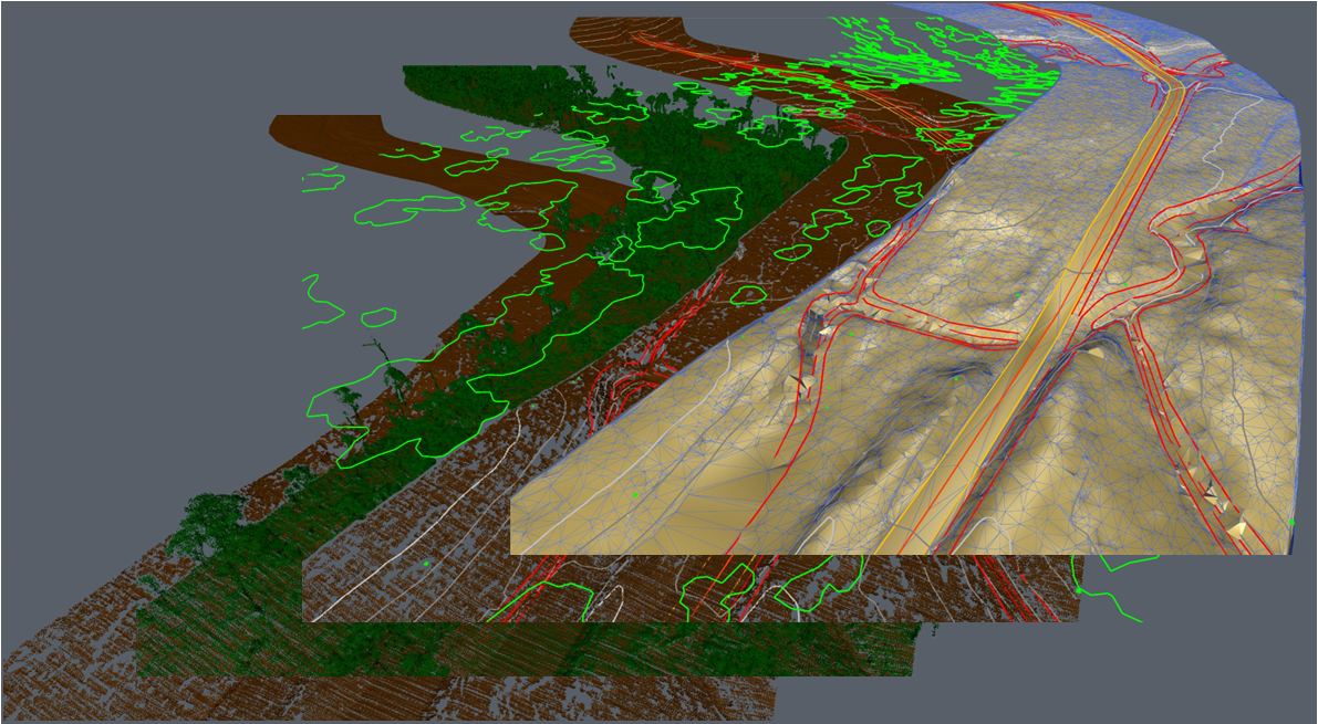
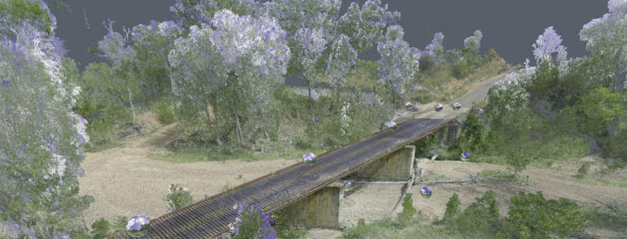
Diospatial developed a spatial survey solution that utilized drone LiDAR, terrestrial laser scanning and ground based survey. Drone LiDAR was used to capture the terrain of the land and imagery, and terrestrial laser scanning was used to accurately capture culverts at approximately 45no. water crossings and 2no. bridges.
The final 3D reality model was hosted on a web-based Digital Twin platform, Pointerra. This allowed project stakeholders to visualize and collaborate on the 3D model and without the need for specialist software or powerful computing hardware.
Multiple survey techniques were used to capture and deliver a complete geospatial data set that could be used by multiple project stakeholders for design of road upgrades, assessment of bridge load capacity and planning of project works.
SURVEY COORDINATION
Prior to any ground survey and aerial capture activities, a primary control network was established in accordance with the ICSM Guidelines across the twelve areas.
Across the twelve capture areas two suitable state government control marks were found and surveyed for localisation of control coordinates.
DRONE LIDAR SURVEY & IMAGERY
Drone LiDAR was used for its ability to penetrate vegetation and capture a vast area efficiently. Drone LiDAR was captured at a high point density and classified for ground and non-ground returns. From this the digital terrain model was produced and topographic features were extracted to produce linework.
The terrain modelling and linework was then combined in to a complete 3D data set to show the complete picture.
Drone LiDAR was also used for its ability to capture colourised imagery of a large area and produce an ultra-high resolution orthophoto and a general level reality model that could be used for site visualisation.
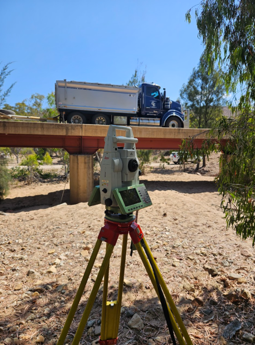
LOAD DEFLECTION SURVEY OF BRIDGES
Load deflection survey was required of three bridge structures. Prisms were placed on the bridge structures at key points of interest. Measurements were taken at pre-load (baseline), during and post-load multiple times in a process called ‘measurement sets’ to achieve the required precision for the survey.
The deflection results were tabulated and assessed to achieve sub 1mm 3D accuracy or better at 95% confidence interval.
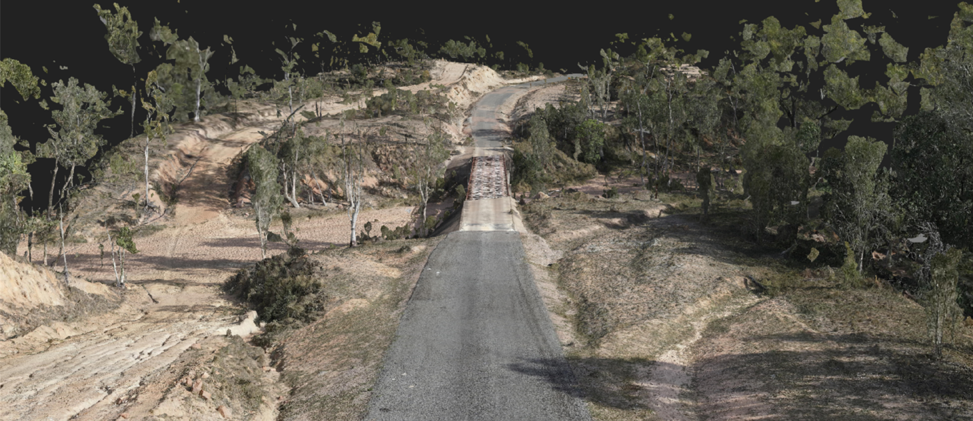
TERRESTRIAL LASER SCANNING
Three bridge structures required high accuracy survey for to be completed as part of the assessment and design for road upgrades. Terrestrial laser scanning was carried out with a Leica RTC360 at maximum point density and with a High Dynamic Range (HDR) images for point cloud colourisation.
Scans were carried out at close intervals around and under the bridge structures to ensure minimal shadowing in the final point cloud deliverables.
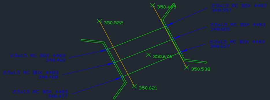
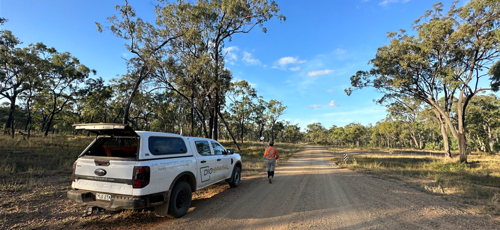
CONVENTIONAL SURVEY
Terrestrial laser scanning was used to survey over 100 water crossings and culverts throughout the survey area. All safely accessible identified culverts and open water crossings were surveyed by either Leica 1” total station or GS16 GNSS receiver (UHF RTK corrections).
The raw data was reduced and quality controlled before being compiled into a single drawing model and delivered to the client as linework and points for use in CAD software.